Flash evaporation
Process Engineering · Entry assessment
Flash evaporation · EVERDA V
This e-learning prepares the dry run before the laboratory experiment. You explain flash evaporation, balance vapour and liquid, read the log-p,h diagram and locate the operating components in the P&I flow chart.
01 · What happens during throttling
A subcooled liquid is throttled from to the lower pressure . Throttling is approximately adiabatic, involves neither work input nor work output and is therefore isenthalpic; changes in kinetic and potential energy are neglected. Part of the liquid evaporates instantly. Gravity separates saturated vapour and boiling liquid in separator B1.
Schematic trend; reference at 0.30 bar(a): approximately 5% vapour and 95% liquid.
Which statement correctly describes flash evaporation?
The throttle lowers the pressure. At the new pressure p₁, the inlet enthalpy lies in the two-phase region, so part of the liquid evaporates instantly.
Which application is named in the laboratory manual?
Non-volatile salt does not enter the vapour phase. Condensation yields salt-free water.
02 · Mass and energy balances
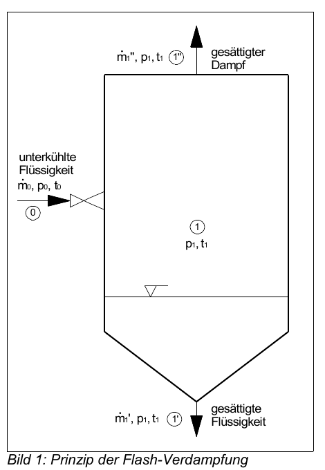
Read the control volume first
- Identify the single inlet 0.
- Distinguish the two outlets: boiling liquid 1′ and saturated vapour 1″.
- Use steady state: neither mass nor energy accumulates in the separator.
Derive both balances in the subtasks below the diagram. The equations appear only after your correct selection.
Which steady mass balance is correct?
One inlet, two outlets and no accumulation:
Which quantities multiply the mass flow rates in the steady energy balance?
Each energy flow is mass flow rate times specific enthalpy; with no accumulation:
Both balances derived
Only now add the definition that leads to the segment ratio in the next module:
03 · Theoretical vapour fraction in the log-p,h diagram
Task: First use the pressure levels p₀ and p₁, the saturation dome and the vertical line at h₀ for orientation. Then decide which of the four blue markers represents the randomly described location and select exactly that marker.
Find the requested state in the diagram.
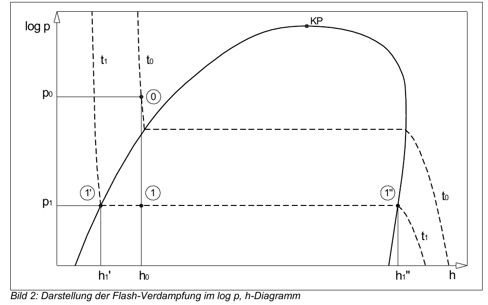
Throttling is isenthalpic: state 0 drops at constant h₀ to pressure p₁ in the two-phase region. The segment ratio gives:
Table basis used by the VDI Heat Atlas: IAPWS-IF97. All pressures are absolute; 0.09 bar(a) equals 0.009 MPa. h₁′ and h₁″ belong to the same saturation state p₁, t₁. h₀ belongs to the subcooled liquid at p₀ = 1.00 bar(a), t₀.
Calculate the theoretical vapour mass fraction as a percentage.
04 · Real vapour fraction and real factor
The condensate is weighed. The liquid feed follows from density, volumetric flow and measuring time:
Calculate the real vapour fraction as a percentage.
Calculate the real factor β.
05 · Match the plant components
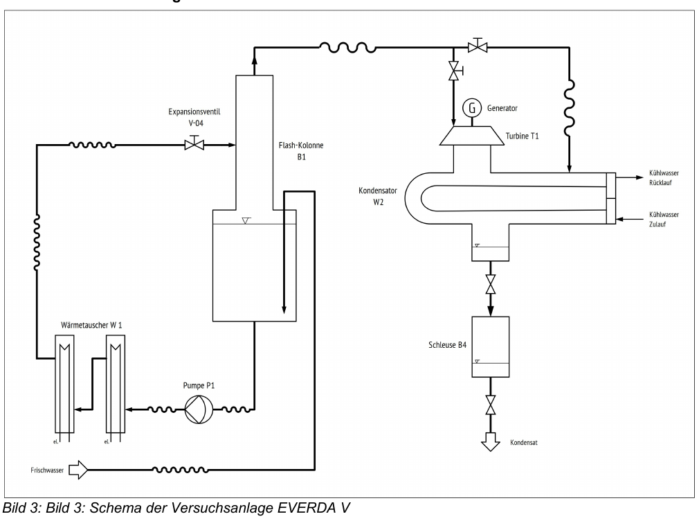
Match each component to its main function.
Preheat the feed water
Circulate water
Reduce the pressure
Separate vapour and liquid
Condense the vapour
Discharge condensate periodically
W1 preheats · P1 circulates · V-04 throttles · B1 separates · W2 condenses · B4 discharges condensate.
What is the purpose of turbine T1 when it is connected into the vapour path?
T1 expands the vapour. The resulting shaft work drives the coupled generator G; the vapour then flows to condenser W2.
Why is the lock mechanism necessary for discharging the condensate?
The lock chamber is alternately isolated from the vacuum side and from the surroundings. This allows condensate discharge without continuously equalising the low plant pressure with ambient pressure.
06 · Dry run on the P&I flow chart
Read the described function, determine the matching component in the large diagram yourself and select its adjacent label; the arrow points to the unobscured original component. The question deliberately does not reveal its name or tag. The sequence summarises the plant-related items from the official checklist; switching actions outside the diagram remain in the PDF checklist.
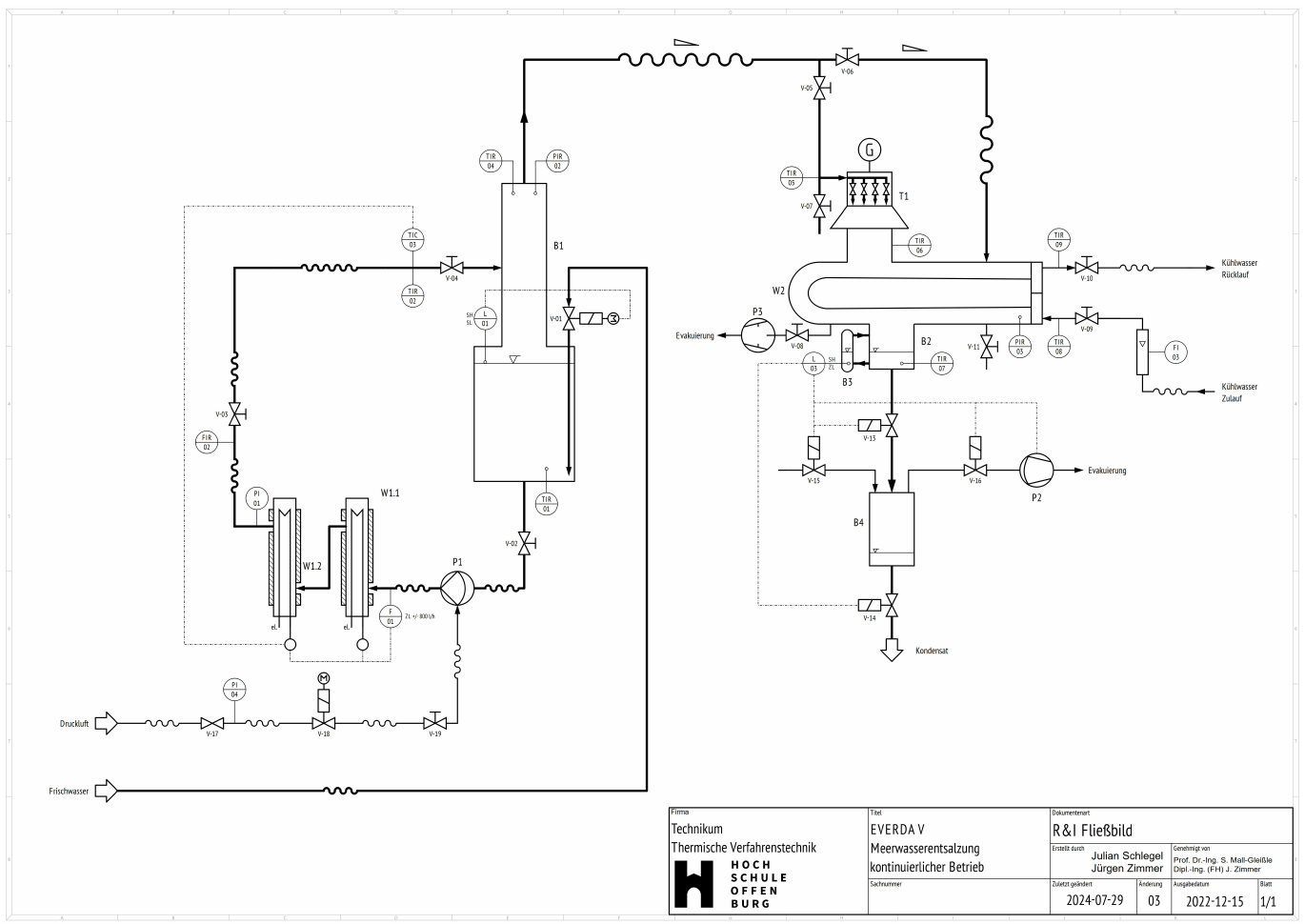
What the full checklist additionally covers
Main switches, acquisition PC and 20 s cycle, the complete initial valve lineup, compressed air and flow monitor, cooling and make-up water, emptying and weighing the condensate bucket, venting the heaters, waiting for steady state, repeating the measurement series, and the seven shutdown steps. Always use the original dated 21 October 2025 at the rig.
The plant operates without the turbine. Which valve lineup routes vapour directly to W2 through the bypass?
According to the manual, V-05 remains closed and V-06 routes vapour through the bypass to condenser W2.
07 · Control PDF
The verifiable PDF is enabled only after all six modules have been passed. It contains the completion status and the answers that were actually checked.
| Module | Status |
|---|---|
| 01 · Principle | Open |
| 02 · Balances | Open |
| 03 · log p,h | Open |
| 04 · Real operation | Open |
| 05 · Plant | Open |
| 06 · R&I-dry run | Open |
Still locked: complete all six modules first.